Conventional NDT
Inspection
Conventional Non-Destructive Testing
Magnetic Particle Testing (MT)
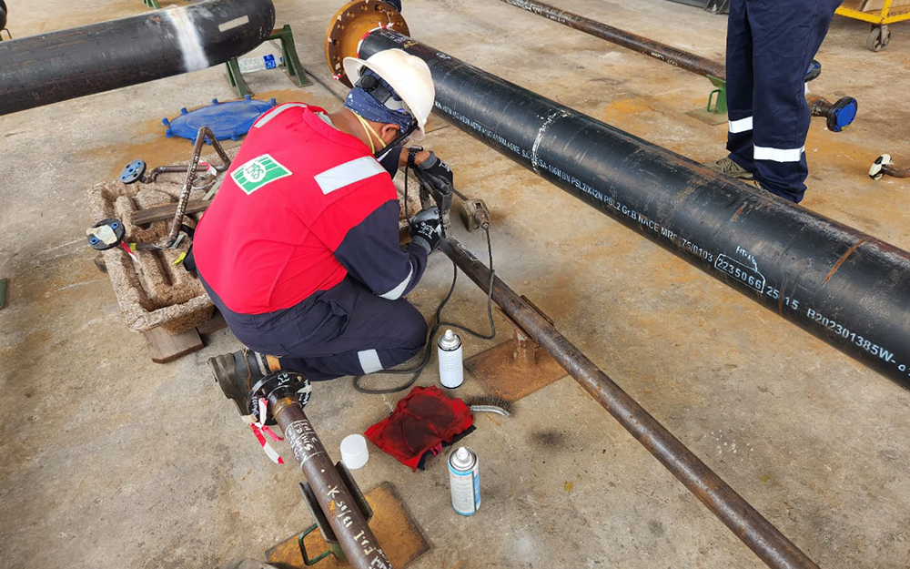
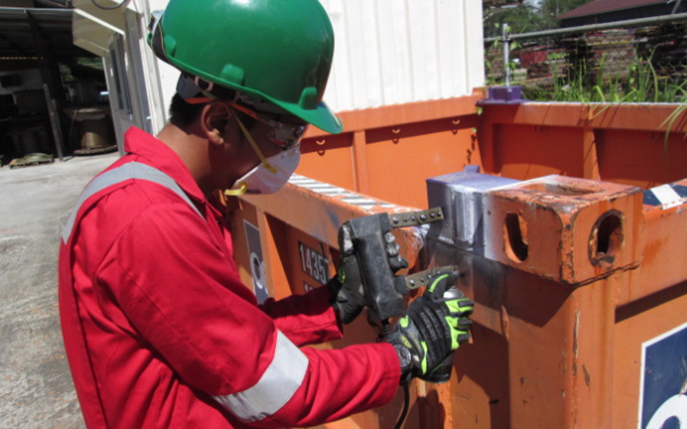
Magnetic Particle Testing (MPT) is a Non-Destructive Testing (NDT) method used to detect surface and slightly subsurface defects in ferromagnetic materials. The process involves magnetizing the material using AC/DC electromagnetic yokes, permanent magnet yokes, or coils. Once magnetized, ferrous particles are applied to the surface. These particles are attracted to areas of flux leakage, typically occurring at discontinuities like cracks or voids, forming visible indications of the defects.
Liquid Penetrant Testing (PT)
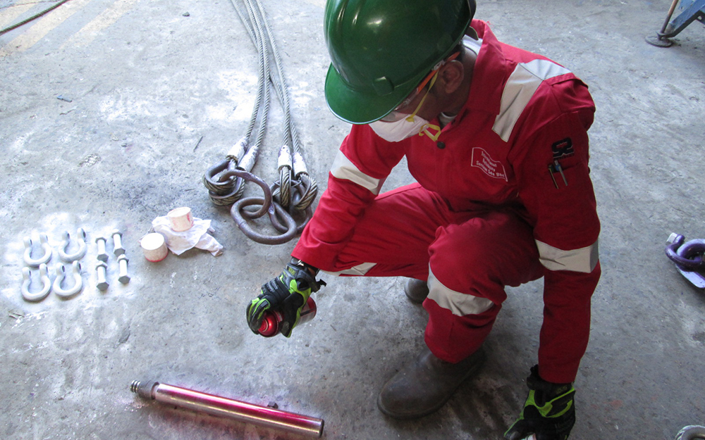
Liquid Penetrant Testing (LPT) is used to detect surface-breaking defects in ferrous, non-ferrous materials and all non-porous materials (metals, plastics or ceramics). The process involves applying a liquid penetrant to the surface of the material, allowing it to seep into any discontinuity such as cracks, porosity, laps, seams and other surface discontinuities. After a specified dwell time, the excess penetrant is removed, and a developer is applied. The developer draws back the penetrant out of the defects, making visible indication on the surface under appropriate lighting conditions.
Radiography Testing (RT)
Radiographic Testing (RT) uses X-rays or gamma rays to inspect the internal structure of materials, components, or assemblies. It is commonly used to detect internal flaws, such as cracks, lack of fusion, voids, or inclusions. Radiographic Testing works by passing X-rays or gamma rays through a material and capturing the resulting image on a radiographic film. Differences in material density and thickness cause variations in radiation absorption, which are displayed as varying shades on the radiograph. In conventional radiography techniques, we use gamma radiation sources like Iridium-192.
Small Controlled Area Radiography (SCAR):
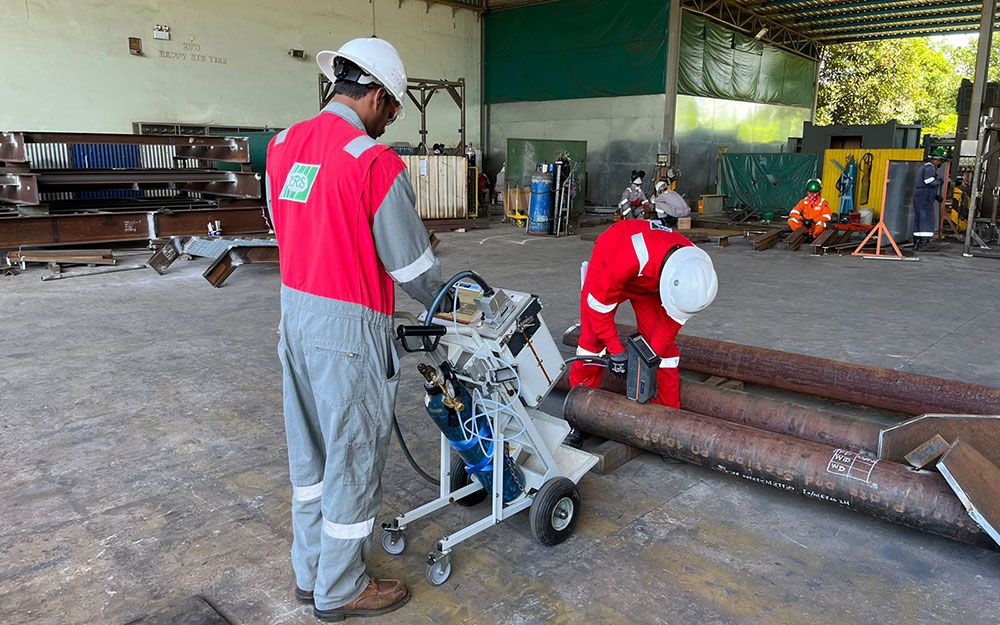
With a restricted area of radiation, Small Controlled Area Radiography (SCAR) with a Selenium-75 source significantly reduces the radiation risk and eliminates the need to evacuate the work area. This means the testing doesn’t affect production targets and daily work schedules.
Radiographic Testing is a critical tool in ensuring the integrity and reliability of components and structures across various industries.
Ultrasonic Testing (UT)
Ultrasonic Testing (UT) is a non-destructive testing (NDT) method that uses high-frequency sound waves to detect internal flaws or to characterize materials. Ultrasonic Testing works by transmitting high-frequency sound waves into a material. Reflections from internal flaws or material boundaries are detected and analysed to determine the presence and location of defects. We provide a wide range of ultrasonic testing services to carry out inspection on castings, forgings, welded components and composite structures in all industry sectors including power generation, oil & gas, construction and chemical etc. Ultrasonics Testing applications includes flaw detection such as inclusions, lack of fusions, cracks, porosity and delamination, Corrosion and Erosion monitoring – Remaining Wall thickness Assessments, Assessment of bond integrity etc.
Visual Testing (VT)
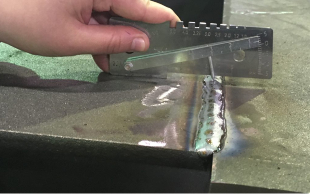
Visual Testing (VT) inspections are some of the oldest and most basic non-destructive testing (NDT) inspection techniques, but are essential to ensure quality control and safe operations.
Visual Testing can be classified as:
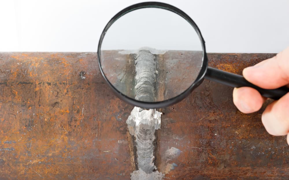
Direct Visual Inspection Involves the use of the naked eye to examine surfaces for defects such as cracks, corrosion, misalignment, or surface finish issues. Often enhanced with magnifying glasses, mirrors, or borescopes to inspect hard-to-reach areas.
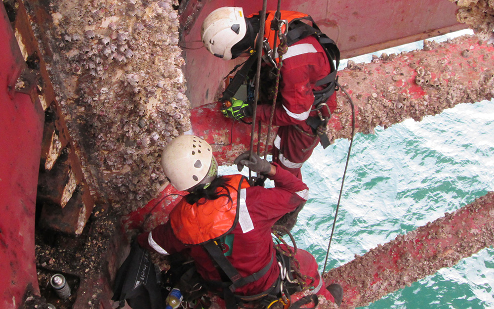
Remote Visual Inspection (RVI): Utilizes equipment like cameras, endoscopes, or robotic systems to inspect areas that are not easily accessible. These tools often come with lighting systems and zoom capabilities to capture detailed images or videos for analysis.
Visual Testing is a fundamental method for ensuring the surface quality and integrity of materials and components across various industries.
Visual Testing Inspections are one of the simplest and oldest forms of Non-Destructive Testing Inspections, but it is also one of the most crucial. Visual Testing can be further categorized as:
Holiday Test
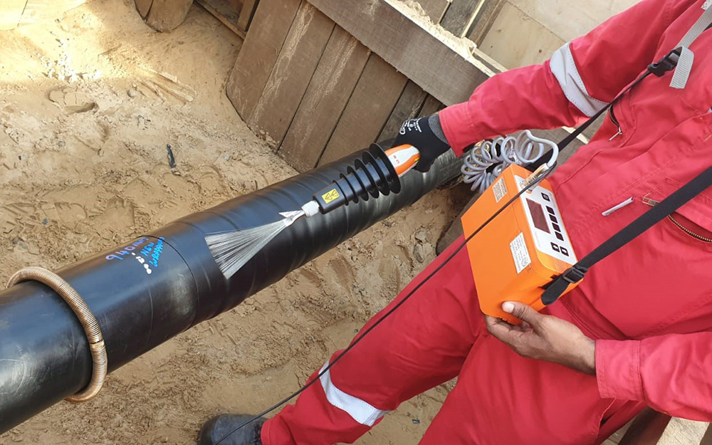
A Holiday Test is an inspection method used to detect discontinuities in painted/coated surfaces using specialized tools and equipment. These tools, called holiday detectors, are portable devices that are swept across the coated surface.
Holidays tests work on the concept of electrical conductivity. Metal substrates are excellent conductors of electricity, and therefore allow current to flow through them. On the other hand, many coatings are poor conductors of electricity and resist the flow of electricity. Using this principle, holiday tests use instruments to locate flaws in anticorrosive paints and coatings.
During Holiday Testing, a ground wire and probing electrode are attached to the same power source. The ground wire is clamped to the specimen being tested while the probe is swept across the surface of the metal substrate. If the probe comes into contact with a coating discontinuity, the exposed metal completes the electrical circuit between the electrode and the grounding wire, resulting in a flow of electricity. This electricity shows up on an indicator, alerting the equipment operator of the defect.
This test is commonly used for onshore and offshore industries where piping and structures are coated with non-conductor coatings.
Eddy Current Testing (ECT)
Eddy Current Testing (ECT) is primarily used for detecting surface and near-surface flaws in conductive materials and weldments. Eddy Current Testing works the principle of electromagnetic induction. An alternating current is passed through a coil, creating an oscillating magnetic field. When this coil is placed near a conductive material, eddy currents are induced in the material. Any discontinuities, such as cracks or voids, in the material disrupt the flow of eddy currents. This disruption changes the impedance of the coil, which can be measured and analysed. Eddy Current Testing is quick, accurate, can detect very small flaws and can be used on complex geometries.
This method good for detecting small surface cracks
This method excels at detecting small cracks near the material’s surface with minimal surface preparation. Its versatility enables application to painted or coated surfaces, making it invaluable in industries such as marine, offshore/onshore structures, cranes, aerospace, manufacturing, and other sectors where protective coatings cannot be removed. It is suitable for both ferrous and non-ferrous materials and serves multiple purposes, including flaw detection, conductivity measurement, metal and coating thickness measurement, and sorting materials by grade and hardness.
Hardness Testing (HT)
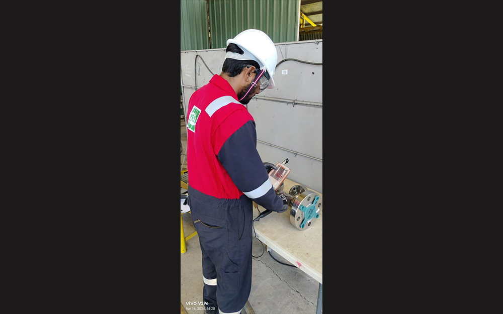
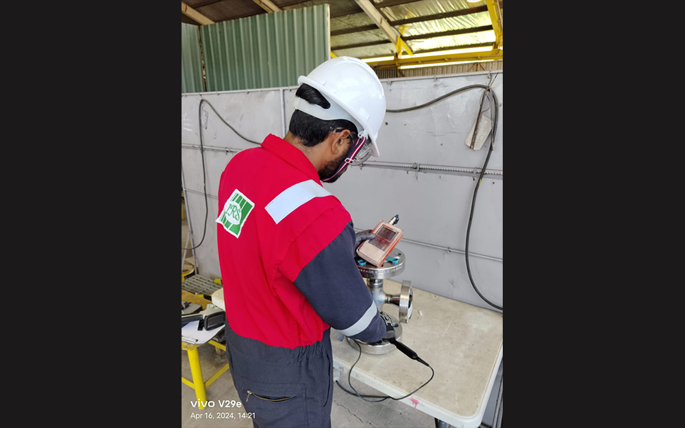
The Hardness Test is the most widely used test for evaluating the mechanical properties of metals and other materials. Our teams are trained in field Hardness Testing, producing immediate results without damage to your components. The purpose of the Hardness Test is to determine the suitability of a material for a given application, conformance to a specification, standard, or particular treatment to which the material has been subjected (heat treatment, thermal process).
There are two different physical methods which are particularly recognized in the practical field:
- Static Ultrasonic Contact Impedance (UCI) method
- Dynamic rebound hardness testing (Leeb).
Hardness Testing is typically performed on new components but can also be used on in-service components to identify any issues. Hardness Testing can reveal susceptibility to cracking as a result of exposure to environmental constituents such as hydrogen sulphide. It can also identify degradation and softening as a result of exposure to elevated temperatures (e.g., fire damage).
Ferrite Testing (FT)
Ferrite is one of the metallurgical phases or components found in the microstructure of both austenitic and duplex stainless steels. Ferrite Testing is a fast, inexpensive, and accurate process that measures the percentage of Ferrite in stainless steel–specifically austenitic and duplex stainless steel. Our material testing technicians evaluate the Ferrite content in your stainless-steel microstructures to ensure proper toughness, corrosion resistance, and crack prevention using the portable Feritscope.
Positive Material Identification (PMI)
Positive Material Identification (PMI) is a non-destructive testing (NDT) method used to verify the composition of metallic materials.
Positive material identification is performed using techniques:
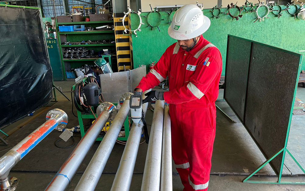
- X-ray Fluorescence (XRF) analyser: This is the most common method and the portability of the hand-held equipment allows IRS to perform PMI on-site at our customers’ premises. The device scans the metal material and identifies its key elements. However, it cannot detect carbon in carbon steels, and is not suitable for identification of pure carbon steel materials.
- Optical Emission Spectroscopy (OES): It is an optical method that can be used to detect almost all types of elements, including carbon and light elements in a variety of different materials including stainless steel, nickel, and carbon steel, etc.
PMI can validate the use of the accurate alloy in manufacturing products/components, detect any instances of incorrect material usage, verify material compliance with the appropriate standards and specifications, encompassing both customer and industry requirements.
Vacuum and Pressure Leak Testing (LT)
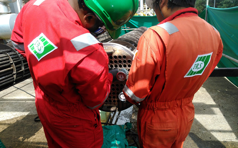
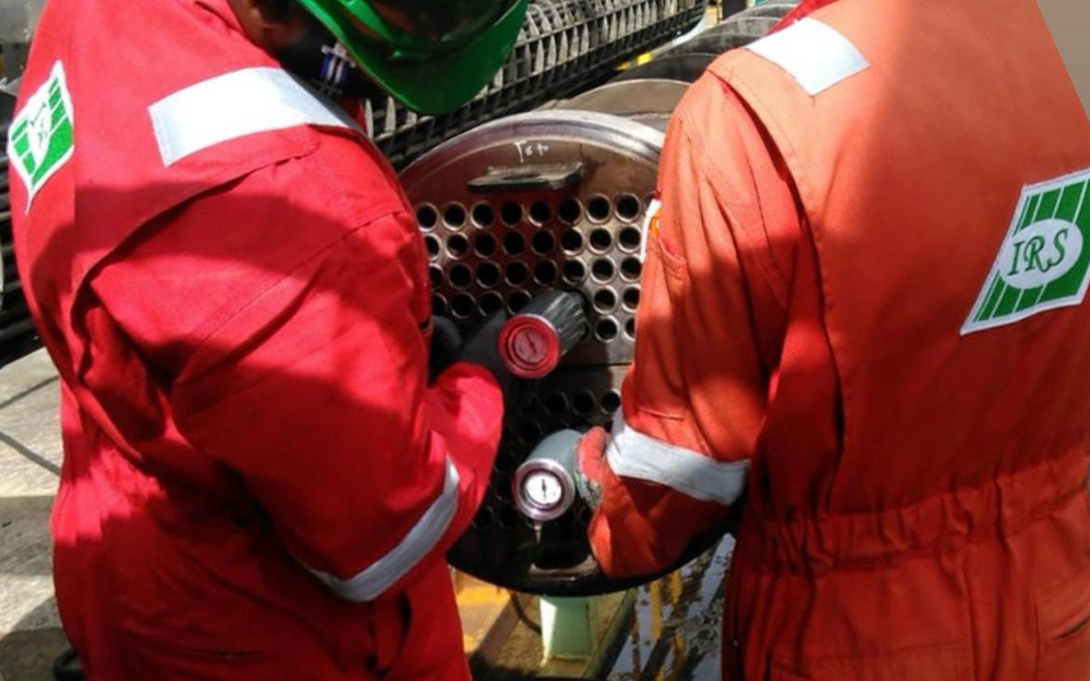
The IRS offers a range of tube leak testing methods for heat exchangers, condensers, and other tubular equipment, including both pressure and vacuum testing.
The IRS pressure/vacuum leak tester provides a straightforward and precise approach for testing tubes in boilers, condensers, and heat exchangers. It is the fastest and most accurate method for identifying leaky tubes that need plugging or replacement.
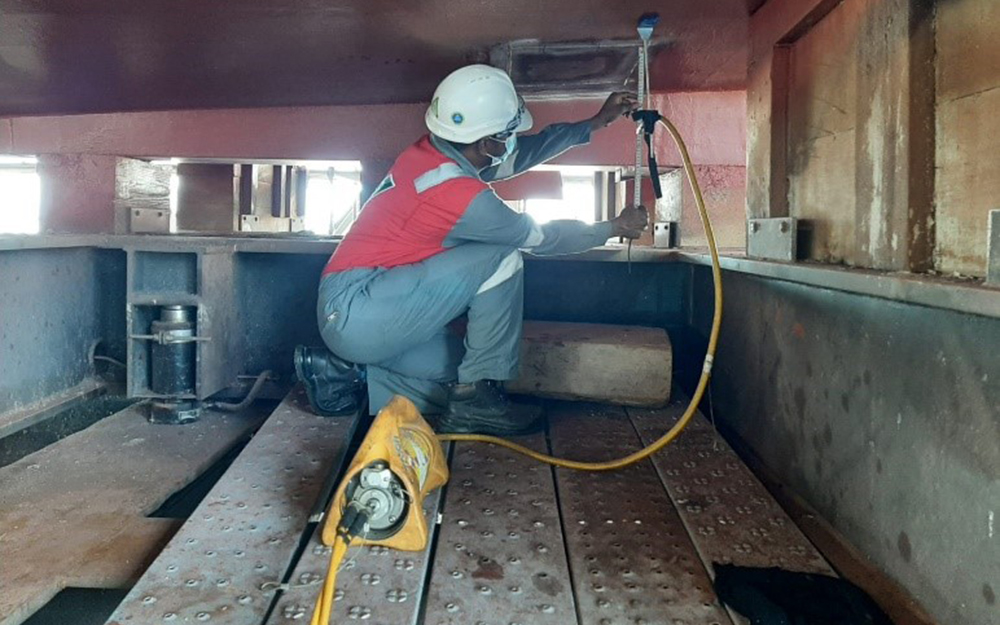
The vacuum tube tester uses compressed air to create a vacuum in the tube, achieving the desired negative pressure on the gauge for at least 5-10 seconds. A stable gauge reading indicates no leakage, while any movement of the gauge pointer suggests a possible through-wall discontinuity.
The pneumatic tube tester uses compressed air to pressurize the tube at a pressure of 2 – 4.1 Bar. It involves injecting air into the tube, plugging the tube from the other end, and holding until the pressure gauge reading stabilizes. A stable gauge reading for at least 5-10 seconds indicates no leakage, while any movement of the gauge pointer suggests a leak.
IRS’s tube leak inspection methods are known for their speed, convenience, effectiveness, and cost-efficiency.

