Advanced NDT
Inspection
Advanced Non-Destructive Testing
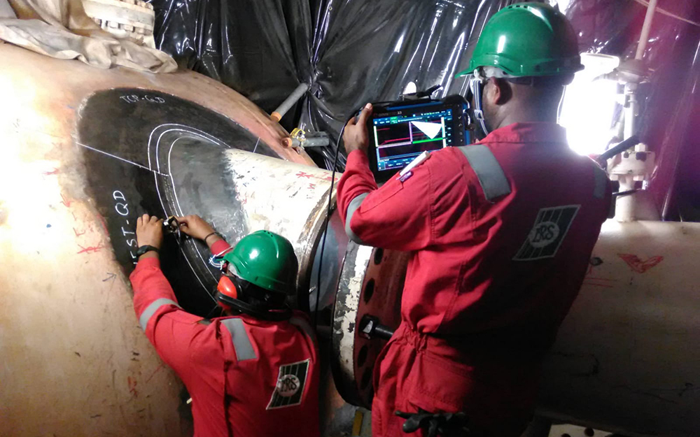
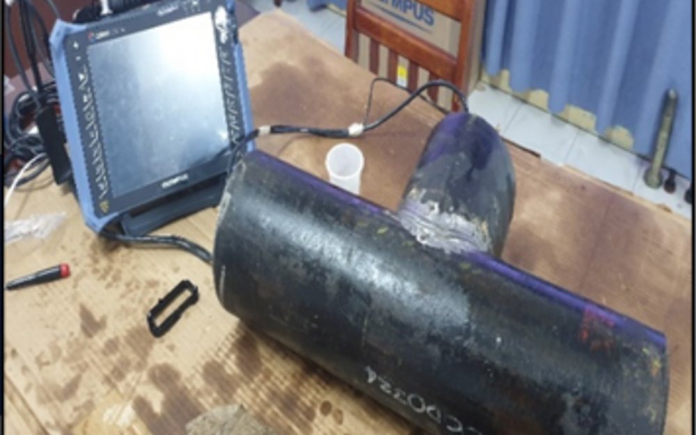
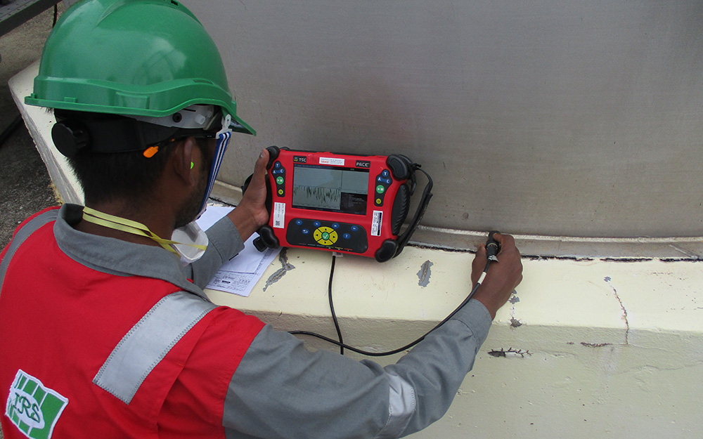
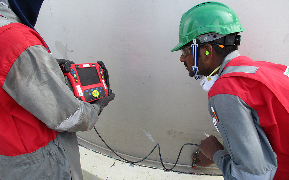
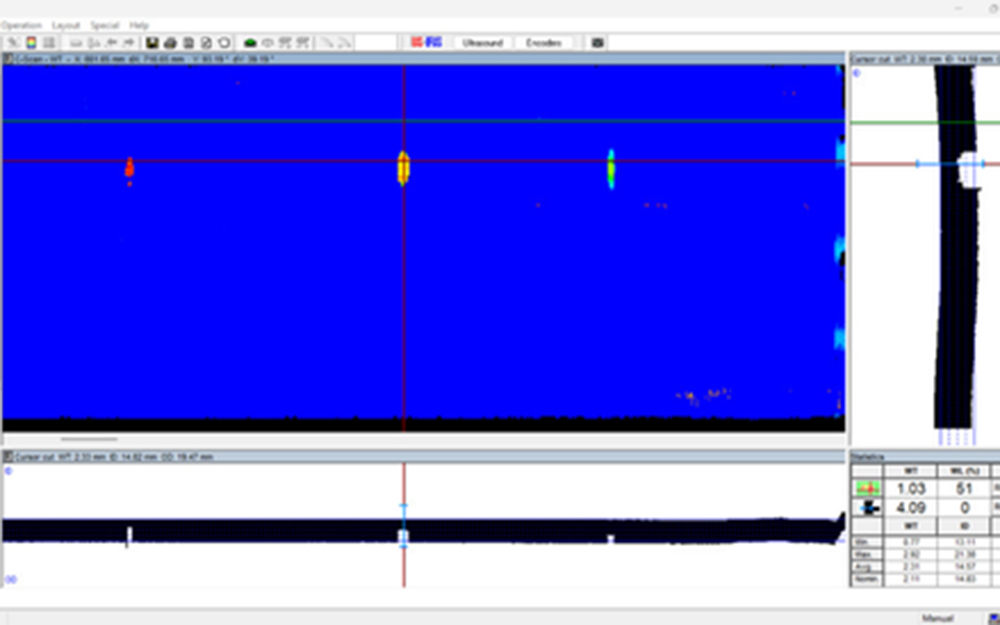
Phased Array Ultrasonic Testing (PAUT)
Phased Array Ultrasonic Testing (PAUT) is an advanced non-destructive testing technique used to inspect materials for internal defects. PAUT employs an array of ultrasonic transducers arranged in a single probe. By controlling the timing and phase of the Ultrasonic pulses emitted from each transducer, the system can electronically steer and focus the ultrasonic beam in various directions and depths without moving the probe physically. This ability allows for detailed scanning and imaging of complex geometries and large areas, providing high-resolution and multiple views as A-Scan, B-Scan, S-Scan and C-Scan.
PAUT’s advantages include enhanced accuracy in detecting and sizing defects, greater coverage area, and the ability to inspect components from multiple angles and positions. It also offers high repeatability and consistency in results. The technique is highly versatile, used in applications such as weld inspections, high-temperature up to 350ºC inspections, corrosion monitoring in pipelines, tanks, and pressure vessels, as well as in-service inspections of various components like flange face corrosion monitoring, bolts inspection, and turbine rotor blades inspection.
PAUT provides significant benefits over conventional methods, including increased inspection speed, portability, and the elimination of radiation hazards, making it a valuable tool in various industries including oil and gas, aerospace, power generation, and manufacturing.
Time-of-Flight Diffraction (TOFD) Ultrasonic Testing
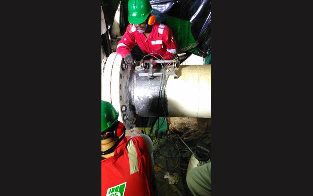
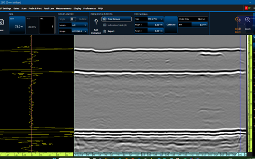
Time-of-Flight Diffraction (TOFD) is a modern and highly accurate ultrasonic Testing Technique employed for detecting flaws in weldments to ensure accuracy of sizing. The use of longitudinal waves, in lieu of shear wave techniques made TOFD more accurate than conventional methods.
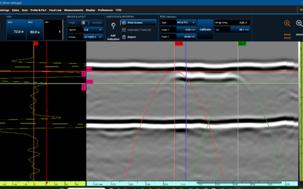
Time of flight diffraction (TOFD) uses ultrasonic Transducer on opposite sides of the weld—one for sending a ultrasonic beam through it and another for detecting reflected or diffracted signals from any defects. TOFD accurately detects and sizes flaws by measuring the time it takes for these signals to travel, even when those defects are misaligned with respect to the original beam of that initial probe.
There are various advantages of TOFD such as a rapid inspection, full volume coverage and adaptable to almost all types/Weld profiles.
This method is especially valuable for testing welds in critical applications such as pressure vessels, power piping and process pipelines. It is also useful in the surveillance of fatigue cracks, stress corrosion and creep crack to allow a safe operation until maintenance will be necessary. TOFD’s accuracy, speed, and adaptability make it an indispensable tool for maintaining the integrity and safety of essential components across various industries.
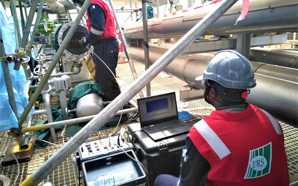
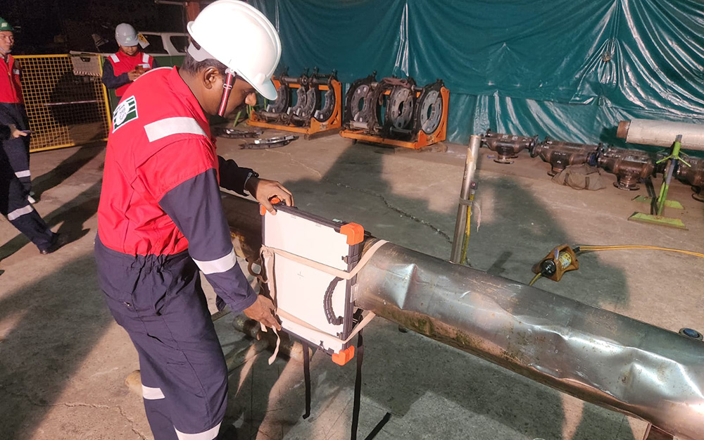
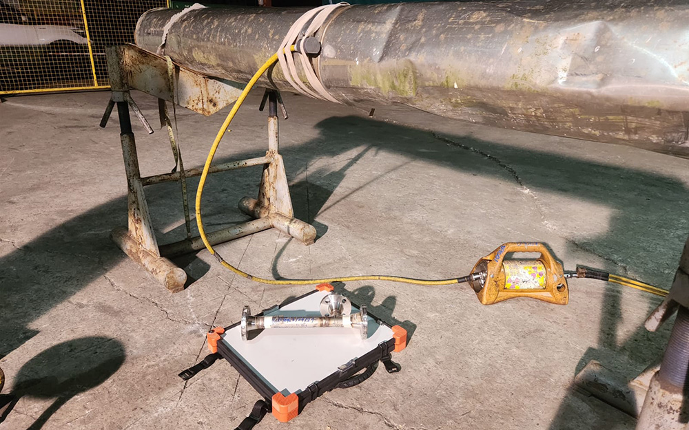
Long-Range Ultrasonic Testing (LRUT)
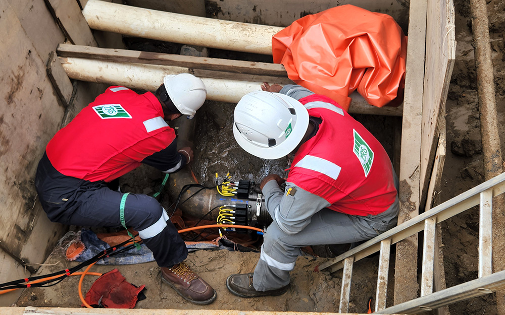
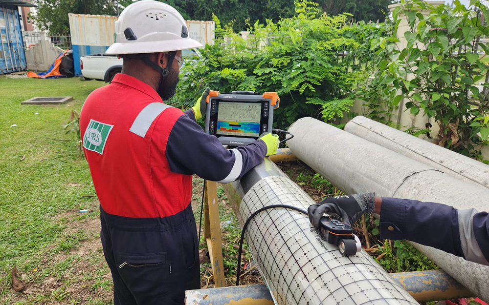
Long Range Ultrasonic Testing (LRUT), also known as guided wave ultrasonic testing, is an advanced and efficient non-destructive testing method for inspecting long lengths of pipe. Utilizing low-frequency ultrasonic guided waves (ranging from 5 to 250 kHz), LRUT can screen hundreds of meters of pipeline from a single location in a single day, inspecting 100% of the pipe wall. This is achieved by fitting a ring of transducers around the pipeline, which generates and receives ultrasonic waves along the pipe’s length.
The low frequency helps generate non-dispersive waves, reducing attenuation and enabling long-range inspection. These non-dispersive waves travel through the pipe wall and reflected back by the defects such as corrosion and other anomalies. These reflected waves are received by the transducers and produce the signal on the screen.
LRUT is especially beneficial as it can be performed on pipes that are in operation, insulated, buried, or in difficult-to-access areas, thus saving time and costs associated with excavation, insulation removal, and scaffolding. The advantages of LRUT include rapid and safe inspection of extensive piping sections, effective detection of corrosion and erosion under insulation with minimal insulation removal, and the ability to inspect pipes in challenging locations such as buried pipeline, and road crossings. It is also suitable for both onshore and offshore pipelines, including tightly packed pipe racks and risers. The technique supports in-service inspections, preventing production losses or downtime.
LRUT is versatile, applicable to insulated piping, buried piping, wharf and jetty piping, offshore piping in splash zones, and pipe penetrations through bund walls. These capabilities make LRUT an invaluable tool for maintaining the integrity of pipelines in various industries, particularly in the oil and gas sector and downstream processing.
Short-Range Ultrasonic Testing (SRUT)
Short Range Ultrasonic Testing (SRUT) is a specialized application of guided ultrasonic sound waves using special types of probes. When the ultrasonic waves hit discontinuities, the mode-converted ultrasonic waves are reflected back and received by the transducer. This technique utilizes higher frequency ultrasonic waves, resulting in higher sensitivity and resolution.
A specially programmed ultrasonic focal law is used to generate short-range guided waves. The probe is usually scanned over a region that is easily accessible and clean from surface irregularities, facing in the direction of the region of interest, which is usually inaccessible due to support structures or the geometry of the test object.
SRUT is particularly beneficial for detecting corrosion on plates and pipes that are inaccessible due to supports, braces, brackets, saddles, legs, or insulation. Ideal applications include rapid detection and sizing of corrosion and erosion in accessible areas under structures such as annular plates, braces, and saddles, detecting metal loss in steel plates and pipe walls concealed under support structures, tank floor annular rings and plates, steels with concrete-coated interfaces, and under pipe support and pressure vessel supports.
Pulsed Eddy Current Testing (PECT)
Pulsed Eddy Current (PEC) is an electromagnetic inspection technique used to detect wall loss in ferromagnetic materials like carbon steel and cast iron. It offers a measure of wall thickness over the probe’s footprint without direct contact with the surface. To generate and capture PEC, a magnetic field is first created by an electrical current in the coils of the probe. This field penetrates through the cladding and any non-conductive insulation (such as concrete, silicate, insulation with a weather jacket, or marine growth) and stabilizes within the component thickness. When the emission is cut off, this abrupt change induces eddy currents that are captured by the probe.
PEC can be applied to in-service assets and can detect damage through insulation and fireproofing, making it an effective tool for assessing corrosion-under-insulation (CUI) and flow-accelerated corrosion (FAC). It is ideal for petrochemical plants, refineries, power generation, and marine applications, including tank floors, pressure vessels, piping systems, offshore platforms, risers, and ship hulls. PEC provides benefits such as minimized accessibility issues and effectiveness through thick materials.
Alternate Current Field Measurement (ACFM)
Alternating Current Field Measurement (ACFM) is a non-destructive testing (NDT) technique used to detect surface-breaking cracks in metals. It operates by inducing an alternating current into the surface of a conductive material, creating an electromagnetic field. When a crack is present, it distorts the electromagnetic field, and this distortion is instantly detected by the ACFM sensor, generating a signal on the equipment screen that provides precise measurements of the crack’s length and depth.
The advantage of ACFM is its ability to detect and size cracks without requiring direct contact with the material or removing coatings, which makes it ideal for inspecting painted or coated surfaces. The non-contact nature of ACFM allows inspections without damaging surfaces and provides real-time feedback, even in challenging environments. ACFM equipment is portable, making it ideal for field use, and is known for its accuracy and reliability. It is widely used in industries such as oil and gas, aerospace, and construction for inspecting welds, pipelines, aircraft components, and infrastructure, ensuring structural integrity and safety in critical applications.
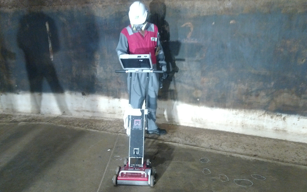
Magnetic Flux leakage Testing (MFL)
Magnetic Flux Leakage (MFL) Testing is widely used to detect surface and near-surface defects in ferromagnetic materials, such as steel, commonly found in pipelines, storage tanks, and other critical infrastructure. The MFL principle involves magnetizing the material under inspection by passing a strong magnetic field through it. When the material is free from defects, the magnetic field flows uniformly.
However, if there are discontinuities, such as cracks, corrosion, or pitting, the magnetic field is disturbed, causing a portion of it to leak out of the material. This leakage field, occurring at the defect site, is detected by sensors placed close to the material’s surface. These sensors capture the leakage signal, which is then analysed to determine the presence, size, and location of the defect.
One of the key advantages of MFL testing is its high sensitivity to surface and near-surface defects, making it particularly effective in detecting small cracks or areas of corrosion that might not be visible to the naked eye. This method also allows for rapid inspection of large areas, making it ideal for applications such as long pipeline inspections or extensive storage tank assessments. MFL testing provides real-time results, enabling inspectors to make immediate decisions regarding the integrity of the structure being inspected. MFL is extensively used in the oil and gas industry to inspect pipelines and storage tanks for corrosion, pitting, and cracks, ensuring the continued safe operation.
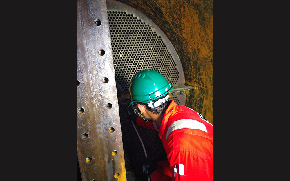
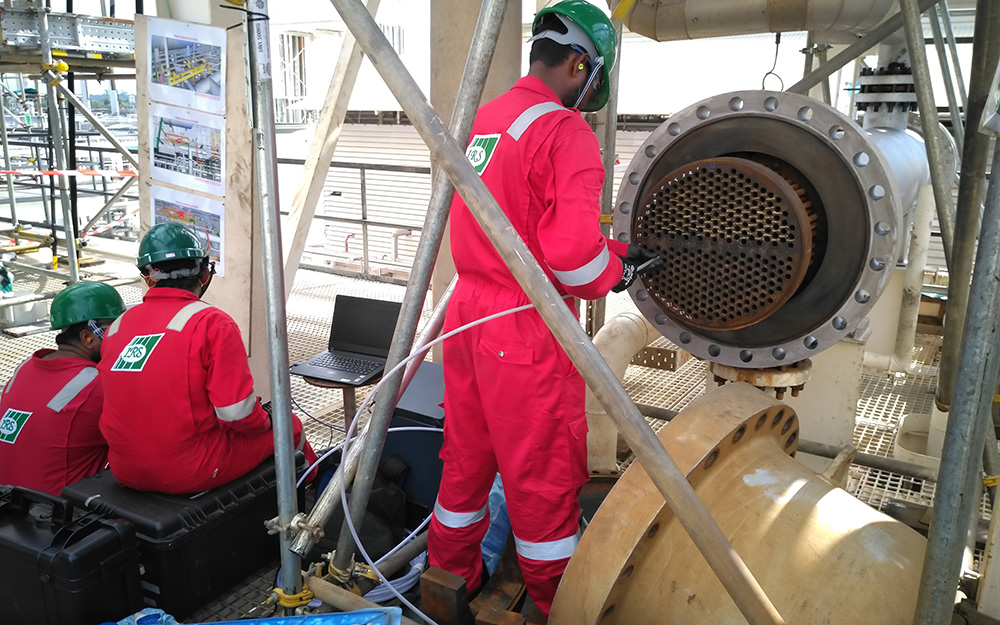
Tube Testing Services
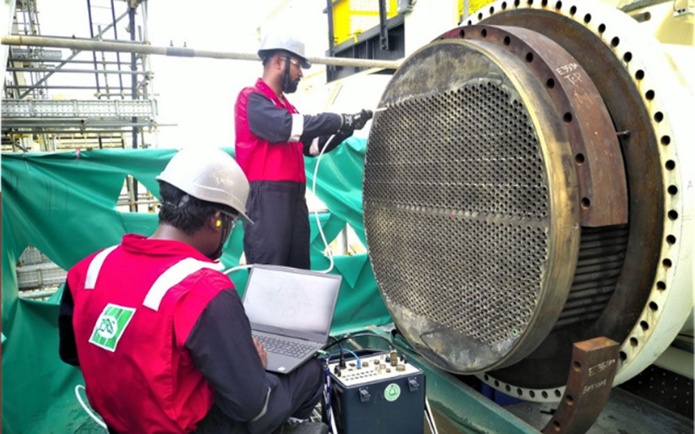
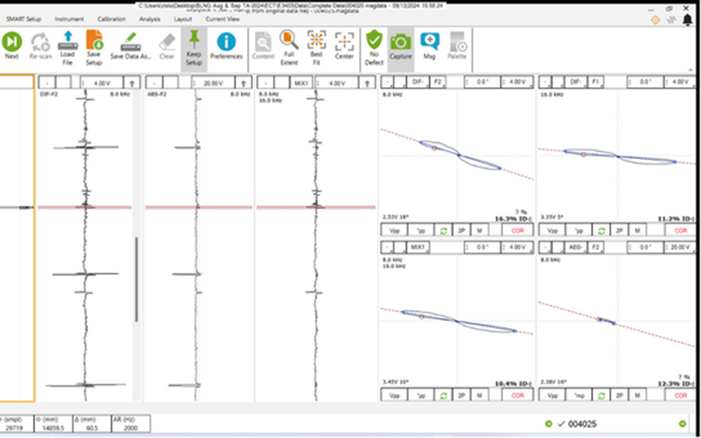
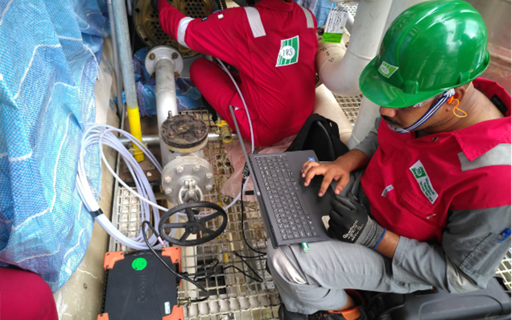
Eddy Current Testing (ECT)
Eddy Current Testing utilizes electromagnetic induction to detect defects in tubes. The principle of Eddy Current Testing involves inducing an alternating current into a probe coil, which creates a magnetic field. When this coil is placed near a conductive tube, it generates circulating currents (eddy currents) within the tube. Any flaws, such as cracks, corrosion, or wall thinning, disrupt these Eddy Currents, causing a change in the coil’s impedance. This change is measured and analysed to detect and characterize defects.
It is the fastest way to assess the condition of non-ferrous tubing in heat exchangers, steam generators, condensers, feed water heaters and evaporators. The inspection is performed swiftly and efficiently, with data collection speeds faster than any other inspection method. Analysis is performed on site and remote to provide immediate results. It is an efficient method of determining the condition and lifespan of tubes, particularly in the power generation, petrochemical, chemical, fertilizer, and air conditioning industries. The technique is used to detect corrosion, pitting, cracks, erosion, and other changes to the interior and exterior surfaces of the tube.
Eddy Current Array Testing (ECA)
Eddy Current Array (ECA) is an advanced version of conventional eddy current testing (ECT), offering improved detection capabilities, speed, and coverage. The Eddy Current Array probe utilizes several individual coils placed around the circumference of the probe and excites them in sequence to eliminate interference, allowing for 100% coverage around the tube’s internal diameter.
ECA can inspect a larger area in a single pass, improving defect detection, especially for small or complex flaws, and providing higher resolution images, including a 3D C-scan of the tube showing the overall topography of any defects that may be present, for more accurate analysis. This technique is good for the detection of axial crack, circumferential cracks, and provides better accuracy for gradual wall losses. It is versatile and can be used on various tube materials and configurations, making it suitable for different industries. ECA tube testing is widely applied in inspecting tubes of heat exchangers, condensers, and boilers in various industries.
Internal Rotary Inspection System (IRIS)
IRIS is an ultrasonic technique employed to evaluate the remaining wall thickness of tubes and pipes. This technique is suitable for both ferrous and nonferrous materials. An IRIS probe is inserted into a tube flooded with water. The probe is fitted with a transducer that generates an ultrasonic pulse along a path parallel to the axis of the tube. A rotating mirror directs the ultrasonic pulse into the tube wall. The mirror is driven by a small turbine that is rotated by the pressure of water pumped into the tube. The ultrasonic pulses are reflected by the inner-diameter (ID) wall and outer-diameter (OD) wall of the tube, and the time-of-flight difference between the two diameters is used to calculate the wall’s thickness.
As the IRIS probe is pulled, the spinning motion of the mirror results in a helical scan path ensuring full coverage of the tube. It is ideal for detecting corrosion, erosion, pitting, and wall loss. IRIS offers benefits like accurate wall thickness measurements and detection of internal and external defects. IRIS can complement other inspection methods or be used whenever initial inspection results indicate the need for further detailed analysis and verification. It is widely used in industries such as power generation, petrochemical, and oil and gas for inspecting heat exchanger tubes, boilers, and other critical piping systems.
Magnetic Flux Leakage Testing (MFL)
Magnetic Flux Leakage Testing (MFL) is a technique used for inspecting tubes made of ferrous materials, typically applied as a fast-screening method when small diameter pitting is expected. The MFL probe contains permanent magnets that create a magnetic flux field in the tube wall. Defects disrupt the magnetic field, causing some flux to leak out of the tube wall, which is then detected by the coils and Hall-effect sensors in the probe.
The size of the leakage field, influenced by the probe’s pull speed and the defect’s shape, dimensions, and location, is presented on a computer screen. Benefits of MFL testing include its ability to inspect finned tubes, applicability to all ferromagnetic materials, good sensitivity to ID pitting, corrosion, erosion, and circumferential cracks. MFL is ideal for the rapid inspection of aluminium-finned tubes and all ferromagnetic heat exchanger tubes, including heat exchanger tubes and air fin fan coolers.
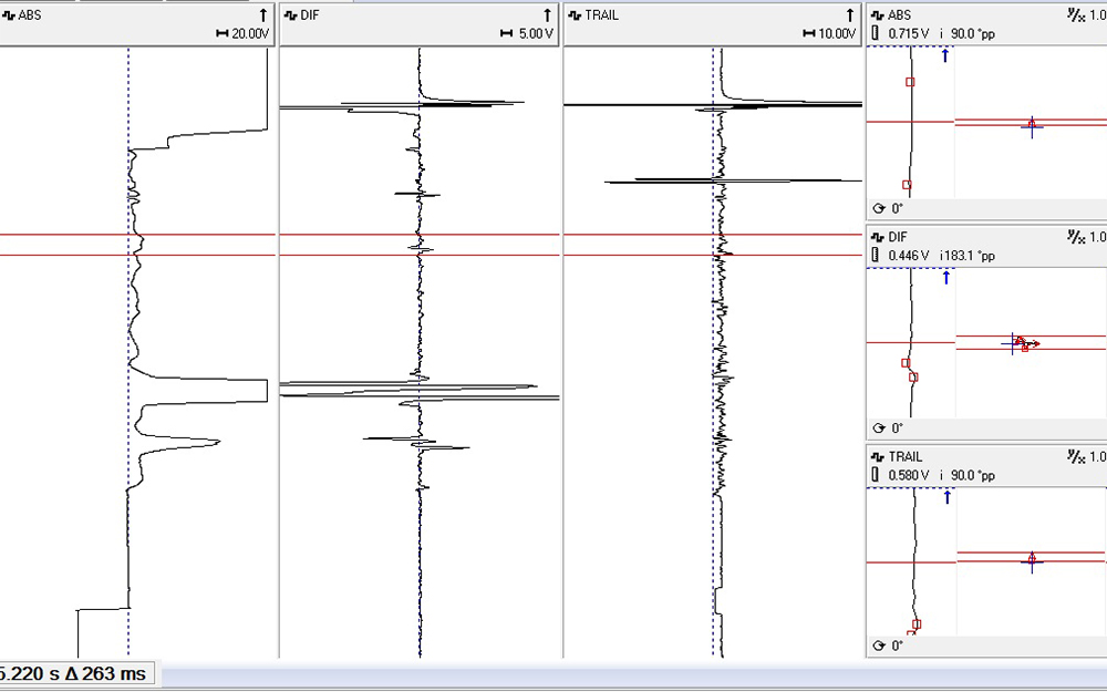
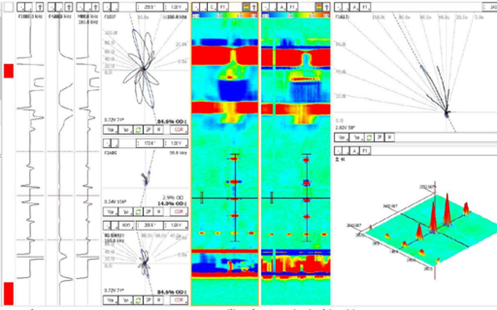
Near Field Testing (NFT)
Near Field Testing (NFT) is an electromagnetic technique which is specifically designed to inspect air cooler (Fin Fans) tubes found in the Oil & Gas industries The technology employs two coils—a transmitter and a receiver—where the receiver is positioned near the transmitter to take advantage of the near-field zone, inducing strong eddy currents axially and radially in the tube wall. The basic probe consists of one driver coil and three receiver coils, providing both absolute and differential signals proportional to defect depth and size.
NFT offers several benefits, including the ability to detect discontinuities near support plates and tubesheet with high sensitivity, and its speed compared to other electromagnetic testing methods. NFT is not influenced by external support structures or tubesheet and it can detect both pits and overall wall loss. NFT is ideal for inspecting fin-fan heat exchanger tubes, particularly aluminium-finned carbon steel tubes, and is excellent for detecting internal discontinuities such as corrosion, erosion, pitting, and axial cracking.
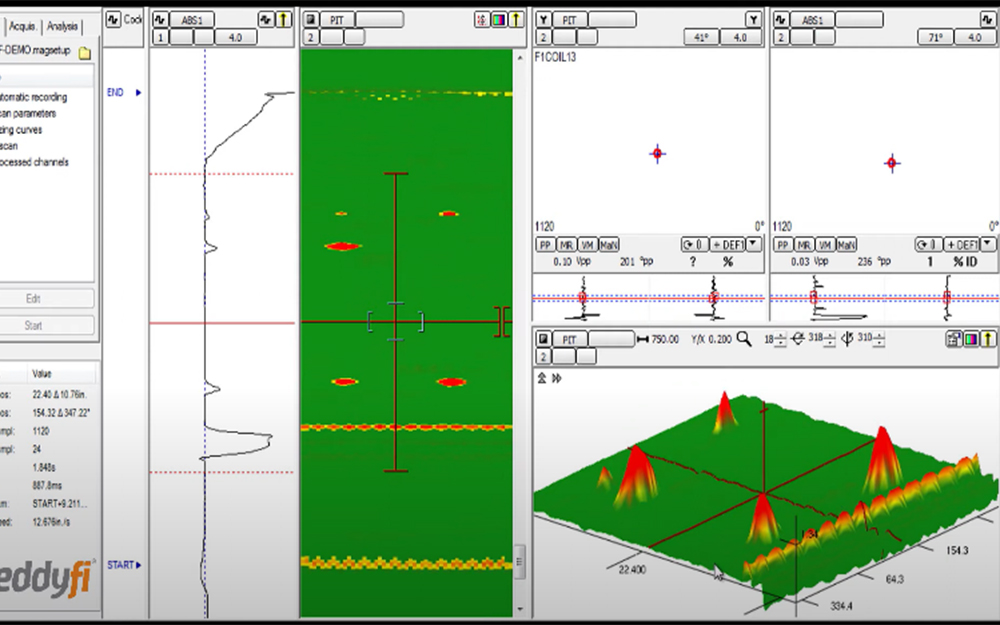
Near Field Array Testing (NFA)
Near Field Array Tube Testing (NFA) is an advanced electromagnetic testing method used to detect discontinuities on the internal surfaces of fin-fan type tubes and ferromagnetic (carbon steel) heat exchanger tubes. Near Field Array probe employs up to 30 coils activated in sequences. An additional tangential coil in Near Field Array allows for detailed data acquisition and detection of discontinuities in all directions.
This method is particularly efficient for inspecting aluminium-finned carbon steel tubes, which are challenging to inspect due to the interference of external aluminium fins with signal quality. It can accurately detect and locate common discontinuities, such as internal pitting, cracks at the tubesheet, internal erosion, and resultant wall loss. Advantages of Near Field Array include providing 2D and 3D ‘C’ scan images for precise measurement of discontinuities size and location, measuring volumetric discontinuities as small as 3mm in a single pass, and detecting both axial and circumferential cracks. It is applicable to a wide range of uses, including ferromagnetic heat exchangers and aluminium fin fan coolers.
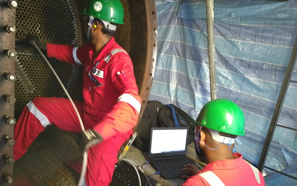
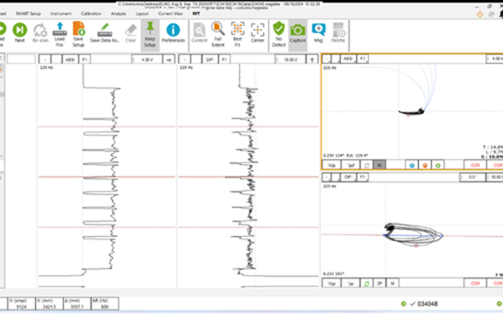
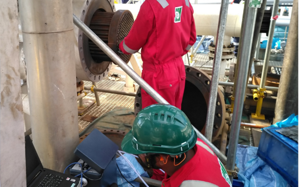
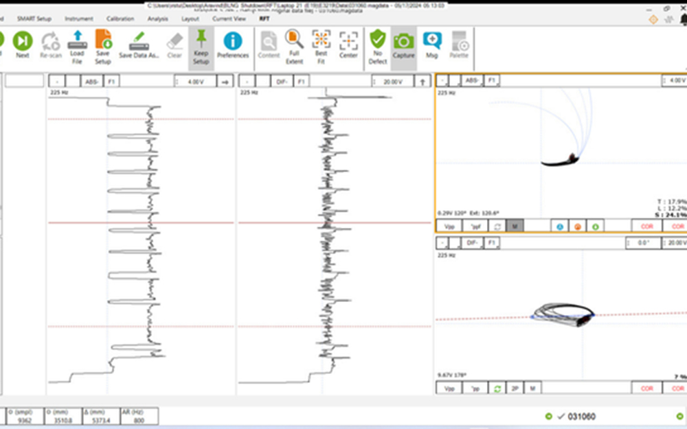
Remote Field Testing (RFT)
Remote Field Tube Testing (RFT) is an electromagnetic testing used to inspect ferromagnetic tubes and pipes such as those in heat exchangers, boilers, and piping systems. The principle of RFT involves generating an electromagnetic field inside the tube using an exciter coil. This field travels through the tube wall, re-enters the tube on the opposite side, and is detected by a receiver coil positioned at a specific distance from the exciter.
Any changes in the electromagnetic field due to defects, causing changes in the signal detected by the receiver. The benefits of Remote Field Testing include its suitability for inspecting ferromagnetic materials and its equal sensitivity to defects on both the inner and outer surfaces. It is highly sensitive to variations in wall thickness. It can operate effectively with lower fill factors compared to Eddy Current Testing (ECT). Additionally, it can detect large-area discontinuities such as steam erosion and baffle wear, making it a versatile and reliable inspection method.
RFT are commonly used in industries such as power generation and petrochemical where it is used to assess the condition of ferromagnetic tubes in heat exchangers, boilers, and other critical systems, ensuring their continued safe and efficient operation.
Digital Radiography (DR)
Digital Radiography (DR) is an advanced form of industrial radiography imaging where digital detectors are used instead of traditional radiographic film, offering immediate image preview and availability. The working principle involves the use of a digital detector to capture radiographic images, which are then converted into digital signals and processed by a computer software to produce high-resolution images.
This method eliminates the need for chemical processing and allows for the enhancement and manipulation of images for better accuracy and resolution. Advantages of DR include faster image acquisition and processing, reduced radiation exposure for radiation workers, enhanced image quality with the ability to digitally enhance and magnify images, and improved storage and retrieval through digital archiving. The technique can detect discontinuities in a range of materials including aluminium, steel, stainless steel, duplex stainless steel, plastics, and composites. Digital radiography is used in all industry sectors, particularly for assessing piping, pressure vessels, and valves etc.
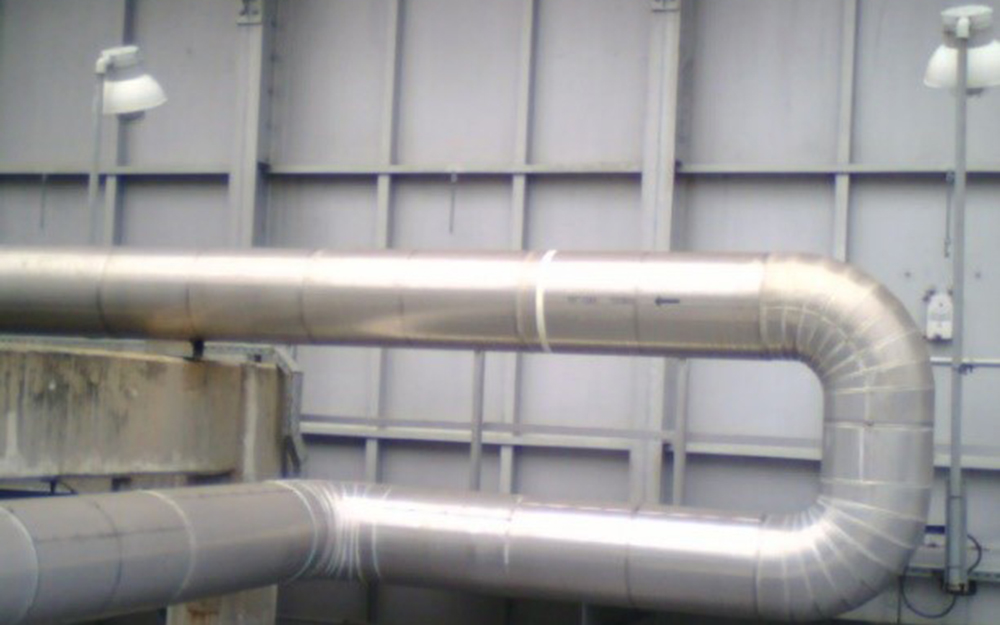
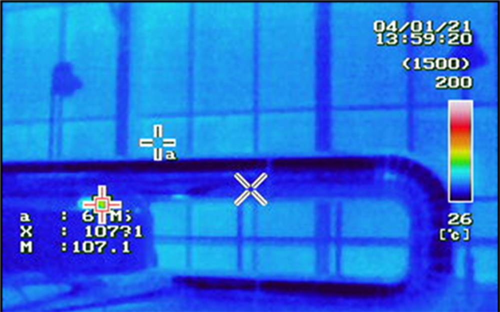
Infrared Thermography (IR)
Thermography Testing used to detect and measure small temperature differences to help find deterioration in assets and plant sites. Thermography can support the maintenance of industrial plants and equipment with its fast and cost-effective application. The working principle involves using an infrared camera to capture the infrared radiation emitted by an object’s surface, which is then converted into a thermal image or thermogram.
This thermogram displays temperature variations, allowing for the identification of thermal anomalies that may indicate underlying issues such as corrosion, erosion, insulation defects, electrical faults, or flaws in materials or structures such as disbands, voids, or inclusions. Advantages of infrared thermography include the ability to perform inspections without direct contact, real-time monitoring, and the capability to cover large areas quickly. Additionally, it is safe, non-invasive, and can be used in a wide range of environmental conditions. Infrared thermography is widely used in various applications, including building inspections to detect heat loss, electrical inspections to identify overheating components, and is utilized in a variety of sectors such as power plants, petrochemical plants, refineries, and the steel industry.
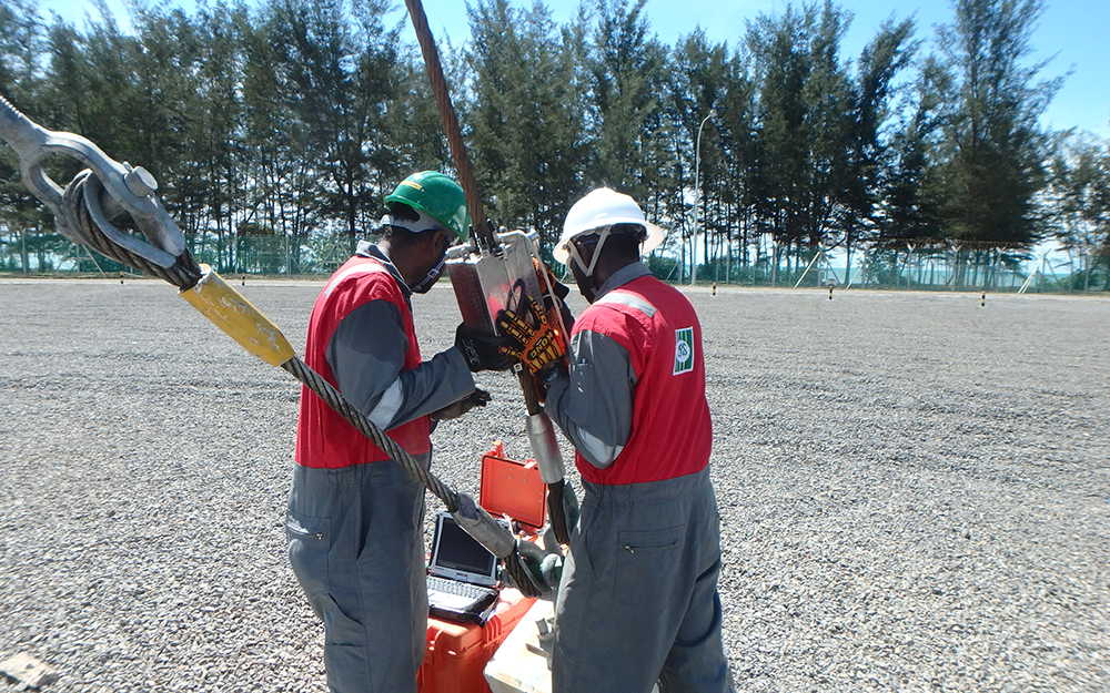
Magnetic Rope Testing (MRT)
Magnetic Rope Testing (MRT) is a crucial method for ensuring the safety of steel wire ropes used onshore and offshore. By fully magnetizing a section of the rope and detecting changes in the magnetic field caused by defects like broken wires, corrosion, wear, or mechanical damage, MRT provides a precise assessment of the rope’s internal condition. This lightweight and portable equipment allows for on-the-spot inspection while the rope is in service, utilizing strong rare earth magnets and sensors to detect discontinuities. MRT measures the Loss in Metallic Area (LMA) and identifies Localized Faults (LF).
Local Flaws (LF) refer to discontinuities such as broken or damaged wires, corrosion pits, or grooves worn into the wires, all of which degrade the rope’s integrity. Loss of Metallic Cross-Sectional Area (LMA) measures the amount of material missing from a specific location on the rope by comparing it to a reference point with maximum metallic cross-sectional area. The advantages of Magnetic Rope Testing include precise inspection of both internal and external defects, fast inspection times leading to shorter production downtimes, high reliability of results, and the portability of the equipment, making it suitable for both onshore and offshore inspections.
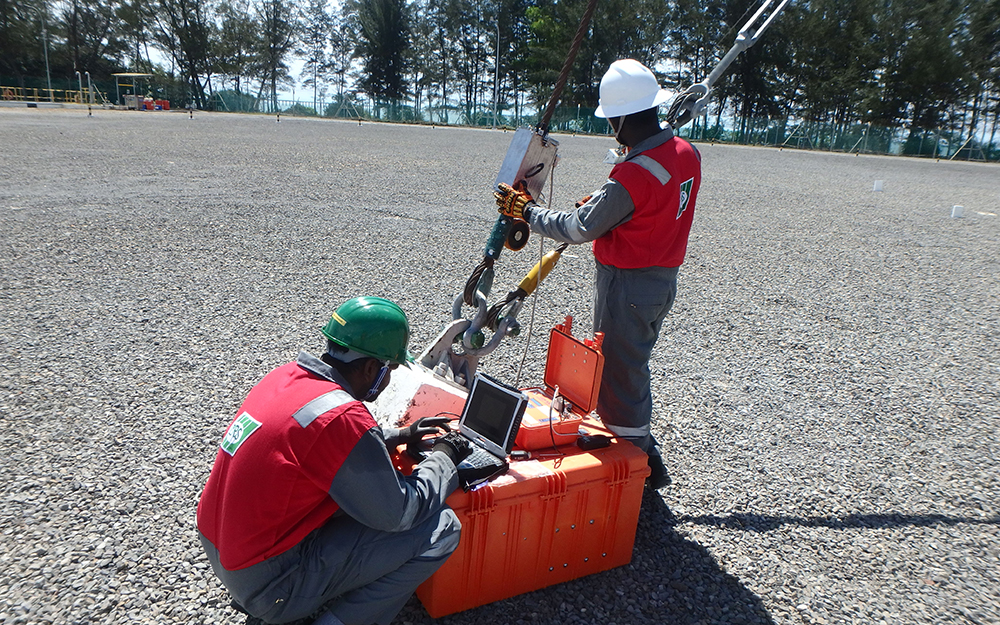
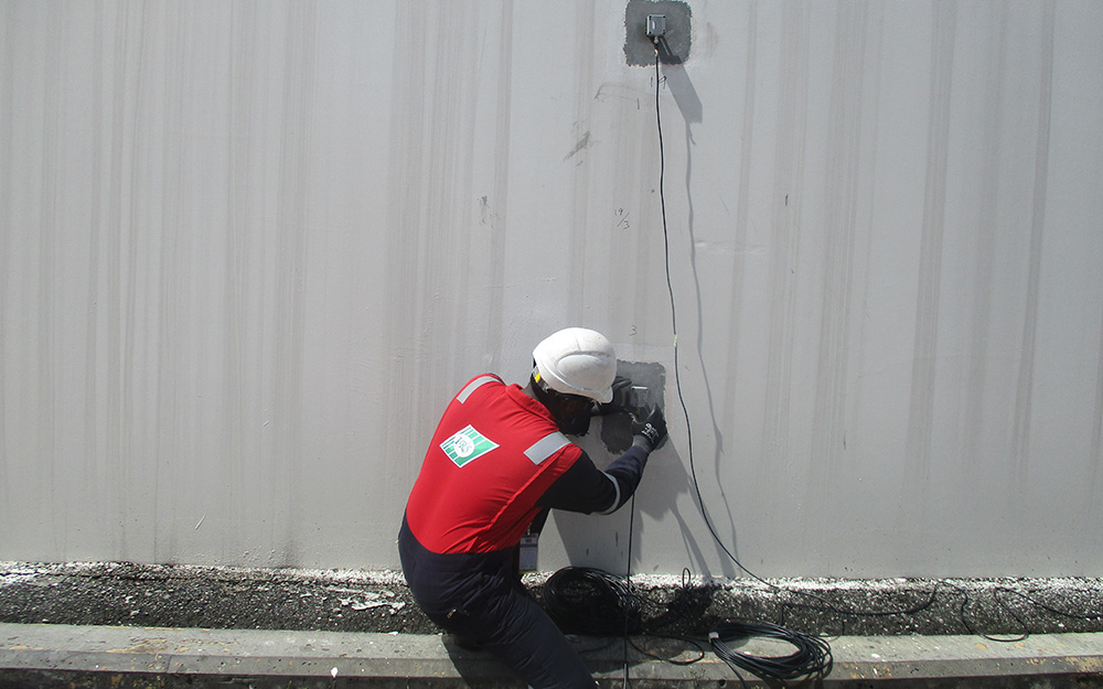
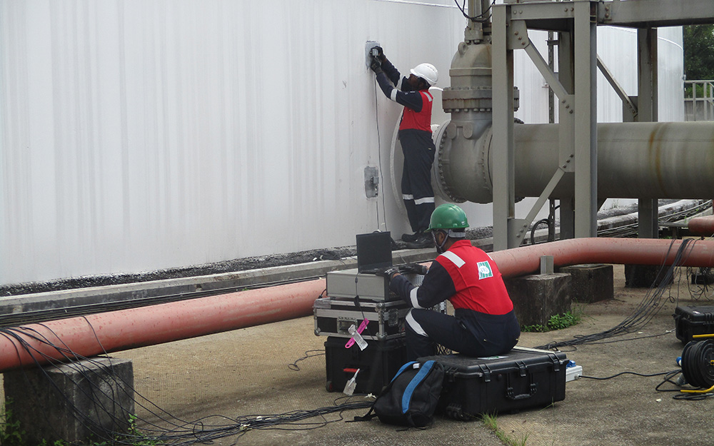
Acoustic Emission Testing (AET)
Acoustic Emission Testing (AET) is a non-destructive method used to monitor the integrity of structures and materials by detecting transient elastic waves generated from localized sources of strain energy under stress. This technique is effective for the real-time identification of active damage such as crack growth, fiber breakage, and corrosion. Acoustic Emission sensors (transducers) detect high-frequency signals from structural defects, and the results are analyzed to accurately locate defects. It provides insights into defect severity and origin, identifying common issues such as active corrosion, crack propagation, hydrogen-induced defects, leaks, and stress corrosion cracking.
The benefits of AE testing include early detection of active damage, real-time asset monitoring, pinpointing defect locations, performing inspections while assets remain online, comprehensive assessment of large structures, reduced costs by minimizing downtime, and non-invasive procedures. Acoustic Emission Testing is a highly versatile and effective method for continuous structural health monitoring of bridges and metallic structures, periodic testing of pressure vessels, pipelines, storage tanks, offshore platforms, and tube leak monitoring. This ensures the safety and reliability of structures and materials across various industries.
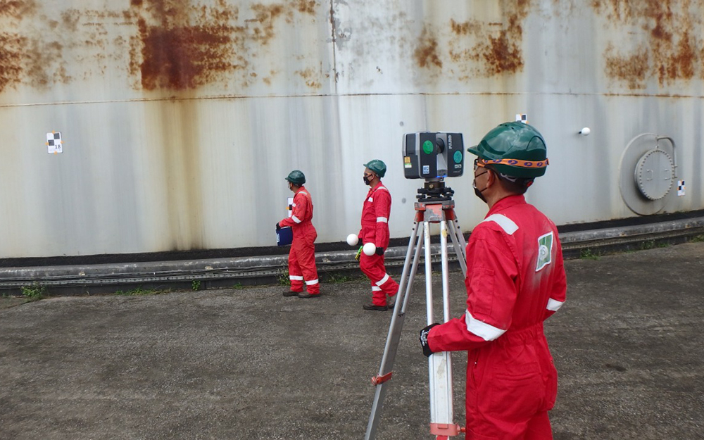
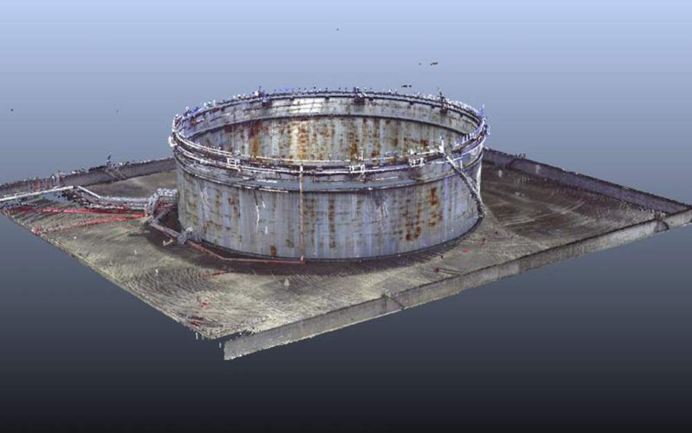
3D Laser Scanning
3D Laser Scanning is a vital tool in construction, engineering, and architecture, transforming real-world sites into digital 3D models. This technology captures the shape, size, and details of objects or environments in three-dimensional space using laser beams. A 3D scanner emits laser beams onto the surface being scanned, measuring the distance between the scanner and the object’s surface by calculating the time it takes for the laser beams to reflect back.
The scanner collects numerous distance measurements from various angles, creating a point cloud that represents the object’s surface geometry. This point cloud is processed using specialized software to generate highly detailed 3D models for purposes such as reverse engineering, quality control, digital preservation, and visualization. We provide 3D laser surveys to clients in industries such as shipbuilding, chemical plants, oil and gas plants, nuclear power plants, and civil engineering. The advantages of laser 3D scanning include high precision, non-contact measurement, rapid data acquisition, versatility, and comprehensive data capture. It provides accurate and detailed measurements, captures data without altering or damaging surfaces, acquires data quickly, applies to a wide range of objects, and captures the geometry, colour, and texture of surfaces for a comprehensive representation.
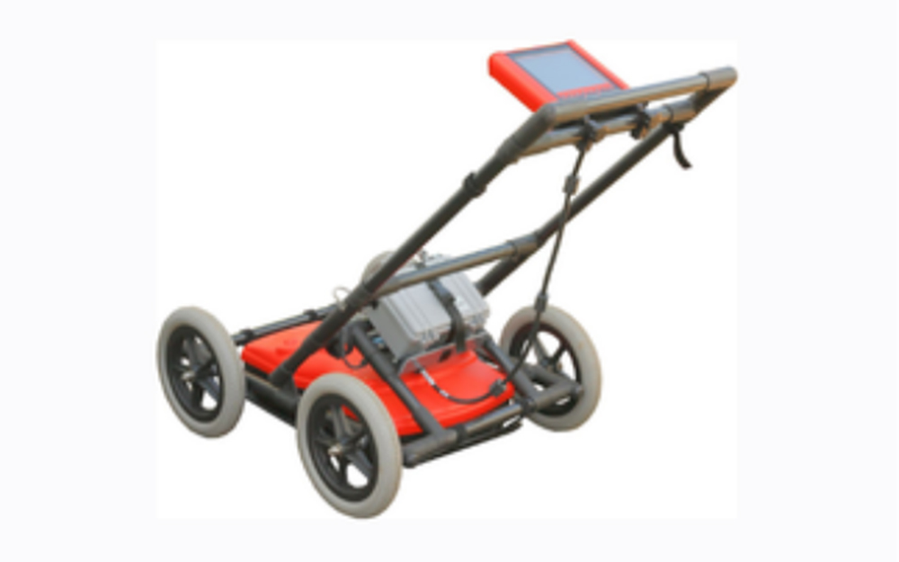
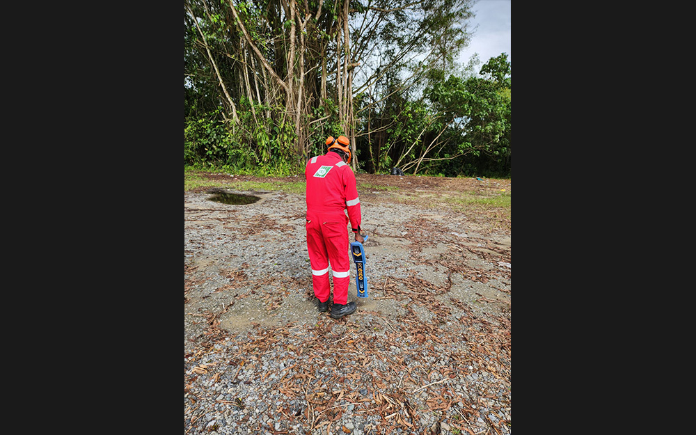
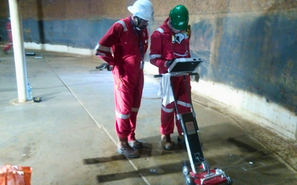
Ground Penetrating Radar (GPR)
Ground Penetrating Radar (GPR) is a non-destructive geophysical method using radar pulses to image the subsurface, widely applied in construction, archaeology, environmental studies, and utilities management. GPR operates by emitting high-frequency radio waves into the ground through a transmitting antenna; these waves reflect back to a receiving antenna upon encountering subsurface materials or objects. The return time is measured to create a subsurface profile.
In construction, GPR locates and maps underground utilities, assesses concrete structures, and identifies voids, rebar, and post-tension cables. Archaeologists use GPR to detect and map buried artifacts, structures, and graves without excavation. Environmental applications include detecting soil contamination, groundwater levels, and landfill boundaries. Utility management uses GPR for infrastructure inspection, locating water, sewer, and gas lines, and identifying leaks.
GPR’s advantages are its non-destructive nature, high-resolution imaging, versatility in various soil conditions, and real-time results for immediate decision-making. GPR services are crucial for safe and efficient subsurface investigations, minimizing risks, and enhancing mapping accuracy.